Read in
9
min
REMI Production: What Teams Get Wrong About Connectivity
“Most broadcast failures are not caused by a single piece of technology breaking. They are caused by the gaps between teams, vendors, and systems that were never designed to work together.” That’s Andrew Ryback, EVP of Production at Broadcast Management Group, writing in May 2026. He’s talking specifically about REMI production (remote integration model), where the production team sits in a control room hundreds of miles from the venue while cameras, graphics, and intercom all route over IP. REMI is no longer a novelty. It’s the #1 technology priority in broadcast for the fourth consecutive year, cited by 41% of 1,300+ broadcast professionals globally (Haivision 2026 Broadcast Transformation Report). The cost case is real: on-site crew requirements drop by 50% or more, and production costs fall by up to 70% compared to traditional OB truck deployments (EAR Professional AV). Adoption is accelerating regardless of whether organizations are ready for it. A lot of organizations aren’t ready. They’ve acquired the encoders, provisioned the cloud infrastructure, trained crews on IP workflows - then handed the connectivity layer to whatever the venue provides, or left it as a detail to sort out on-site. That’s the gap where REMI productions fail. Here’s what the failure patterns look like, and how to avoid them.


REMI Is a Systems Integration Project, Not a Procurement
The most predictable failure mode in REMI isn’t equipment. It’s the assumption that acquiring the right tools means the system will work.
In a traditional SDI production, the signal chain is physical: cables, routers, patch bays, hardware you can trace with your hands. Failures are visible. In a REMI production, the signal chain runs across IP networks managed by multiple vendors, ISPs, cloud providers, and venue operators who have no knowledge of each other. The gaps between those systems don’t show up on a block diagram. They show up on air.
Video contribution typically gets engineered carefully. Encoders are specified, codecs are tuned, SRT parameters are configured. What gets treated as an afterthought: intercom, tally, and camera control signals. These are, in many productions, more latency-sensitive than the video itself.
Director-to-camera IFB (Interruptible Feedback) at 200 milliseconds or above visibly disrupts live performance. Camera operators on-site can’t take direction cleanly. Talent loses rhythm. As Ryback notes: “The signals carrying intercom communications to camera operators on site, control signals to PTZ robotic cameras, and camera shading instructions are critical to the success of a remote production. If they don’t arrive or arrive late, the show may suffer a catastrophic production failure.”
This is a systems integration problem. The video path had a spec. The intercom path ran over consumer VoIP on the venue’s shared Wi-Fi. Nobody was responsible for ensuring the two worked together under live-event load.
Build the integration before the show, not during it. Reliable remote production starts with a connectivity architecture that accounts for every signal path, not just the video feed.
“Best-Effort Internet” Is Not a Production Architecture
Public internet is fast, flexible, and cheap. It is also not designed for live broadcast.
The difference between public internet and broadcast-grade IP transport is the SLA. Dedicated fiber or MPLS circuits come with guaranteed bandwidth, low jitter commitments, and contractual uptime obligations. Public internet, including most venue-provided connections and cellular networks, operates on a best-effort basis. When the network is congested, your traffic gets treated the same as everyone else’s. There is no queue priority for the live feed that goes to air in 90 seconds.
This doesn’t mean public internet can’t work. SRT (Secure Reliable Transport), now used by 78% of broadcast professionals (Haivision 2026), can recover up to 10% packet loss, but only when the latency buffer is tuned correctly for the specific link. Richard Wolf, EVP of Marketing at The Switch (now Gatesair), offers a practical framework: A and B tier high-value sports properties cannot tolerate public internet risk. C and D tier events - corporate conferences, lower-budget sports, regional news - can accept it with proper configuration and redundancy.
The mistake teams make is not choosing public internet over dedicated circuits. The mistake is not auditing what they’re getting. A venue that claims “100 Mbps fiber” may be delivering shared bandwidth that bursts down under event load. Nobody asked for a packet loss test, a round-trip time measurement, or a jitter sample taken during an actual event. The spec sheet said 100 Mbps. The encoder got 4 Mbps upstream when doors opened.
61% of broadcasters using fiber as their primary contribution path also use cellular as a backup (Haivision 2026). The industry standard isn’t fiber or cellular - it’s both. The question isn’t which one you trust. It’s whether you’ve tested both before the show starts.
Understanding why venue-provided internet fails under live-event load is the starting point. The fix is designing around the failure, not hoping it doesn’t happen.
The 5G Reality Check
The 5G-for-broadcast conversation has been running for several years. The technology is real. The hype around it is also real.
Here’s what happened at the Professional Squash Association German Open in 2024. The broadcast center was inside a squash court - physically a building inside a building. Standard bonded cellular backpacks failed. As Open Broadcast Systems documented in November 2024: “Even a simple window can be the difference between 1 Mbps and 10 Mbps per second. Most cellular bonding equipment have tiny antennas, which do not help in low-signal environments.” The solution required roof-mounted PoE routers positioned 100 meters from the broadcast center, connected via LAN cable. The equipment wasn’t wrong. The environment wasn’t accounted for.
Indoor attenuation is only part of the problem. The bigger issue is what “5G” actually means in most broadcast deployments today.
Most live 5G deployments are 5G NSA - Non-Standalone. The 5G radio is real, but the core network is still 4G LTE. No network slicing. No QoS differentiation for broadcast traffic. No priority treatment. For contribution purposes, 5G NSA is functionally 4G with a higher theoretical peak speed that rarely materializes in a congested venue.
Critically, that theoretical advantage disappears on upload - which is the only direction that matters for live contribution. Across our own deployments, 4G LTE has consistently produced more stable upstream performance in crowded indoor venues than 5G NSA. The reasons are structural: 4G has a denser, more mature tower footprint optimized for coverage; the spectrum it uses penetrates buildings more reliably than the higher-frequency bands 5G depends on; and its upload resource allocation is better tuned to sustained throughput under load. 5G’s headline speeds are a download story. Upload in a packed venue is where 4G still wins.
There’s also a compliance issue that rarely gets discussed until it’s too late. Many bonded cellular backpacks use Adaptive Bitrate (ABR) encoding. ABR produces variable bitrate output, and professional downstream receivers require Constant Bitrate (CBR). The mismatch causes jitter that professional receivers won’t tolerate. OBE documented this at the German Open: the bonded backpacks produced streams that required a full re-encode before any taker feeds could accept them. That’s an unplanned processing step in a live broadcast chain.
Where 5G genuinely helps: replacing satellite for news gathering agility, and opening coverage of lower-budget sports events that couldn’t previously afford fiber or satellite backhaul. For those use cases, even imperfect 5G NSA is a meaningful step forward. For mission-critical contribution at high-value productions, run the technology you’ve tested under load, not the spec sheet speed.
54% of broadcasters now use cellular for live video contribution (Haivision 2026). The ones doing it reliably are running enterprise multi-carrier bonded connections, not consumer 5G devices.
Single-Path Contribution Fails. Every Time, Eventually.
A single contribution path, regardless of how good the circuit is, is a single point of failure in a system with zero tolerance for failure.
SMPTE ST 2022-7 - the standard for hitless failover between redundant IP paths - exists because the industry understood single-path risk a decade ago. The standard is mature. Implementation still gets skipped in smaller productions because the second path costs money and “the fiber has never failed before.”
It fails eventually. The question is whether it fails on a quiet Tuesday during rehearsal or during the live championship broadcast.
The practical architecture isn’t complicated. Bonded multi-carrier cellular as either the primary or a tested secondary. Automatic path failover that activates in milliseconds, not a manual switch requiring someone to notice the feed is down and respond. Separate network paths for video contribution, intercom, tally, and return feed so a failure in one doesn’t cascade across the others.
Provisioning a single fiber circuit and marking the connectivity column complete isn’t a finished architecture.
The Upload Math Nobody Does Before the Show
Most pre-production connectivity planning focuses on download speed. Broadcast contribution runs on upload.
A single HD stream over SRT (compressed) requires 2-8 Mbps upstream. A multi-camera REMI setup with 6 contribution feeds using HEVC encoding requires 60-200+ Mbps upstream in aggregate (TVU RPS / LiveU LU800 specifications). A 4K HEVC single stream needs 20-80 Mbps. Add return feeds, intercom, tally, and program monitoring - the upstream requirement compounds fast.
Against that, a single cellular carrier in a congested venue delivers approximately 1 Mbps of usable upload under real event conditions (Dejero bonded cellular white paper, 2025). Consumer SIMs compound the problem: carriers deprioritize consumer traffic when towers are congested, pushing throughput below even that floor.
Enterprise IoT SIMs close part of the gap. Traffic on those SIMs is served before consumer traffic on the same congested tower. That’s how carrier QoS tiering works. In a packed venue where every attendee’s phone is loading the same tower, the difference between consumer and enterprise SIM priority is measurable in available upstream throughput.
Multi-carrier bonding closes the rest. Verizon, AT&T, and T-Mobile running simultaneously draws from three independent tower relationships. If one carrier’s tower is saturated, the other two continue contributing bandwidth. Session persistence keeps active streams live through carrier transitions. For productions running at any kind of volume, this architecture is what makes per-event connectivity predictable.
The upload audit happens before every production: total upstream requirement for all simultaneous paths, mapped against confirmed enterprise-priority capacity on all three carriers at the specific venue. Not a speed test from the office. A load simulation from the actual production position.
SIM Banks vs. Managed Bonded Cellular
There’s a distinction that gets collapsed in conversations about cellular-based REMI connectivity, and it matters operationally.
A SIM bank is a device that holds multiple SIM cards - sometimes from the same carrier, sometimes across carriers - and distributes traffic between them. The traffic management is basic: spread connections, aggregate bandwidth where possible. SIM banks are inexpensive and genuinely useful for low-stakes applications where having more than one cellular path is the main requirement.
A managed bonded cellular solution is different at every layer. The bonding protocol actively monitors link health across all carriers in real time, distributes packets dynamically based on live latency and loss conditions, and maintains session persistence across link failures. The SIMs are enterprise-grade, pre-negotiated with carriers for priority treatment and appropriate data plans for production use. Hardware arrives pre-configured. A Network Operations Center monitors the connection proactively - not reactively after a failure is reported.
For a production company running 30 or 40 events a year, the SIM bank route accumulates real operational overhead: carrier plan management, hardware configuration, field troubleshooting three hours before show time with no NOC to call. The managed route converts connectivity from an engineering variable into a fixed operational input. Same performance at every venue. That’s what made it possible for a school sports streaming operation to scale to over 600 games per year - connectivity stopped being the constraint on volume.
The choice comes down to in-house broadcast IP expertise and production volume. DIY works with the right skills at modest scale. At volume, managed typically wins when operational overhead is honestly accounted for.

What a Proper REMI Connectivity Architecture Looks Like
The components aren’t exotic. The discipline to put them in place before the show is.
Multi-carrier bonded cellular with enterprise SIMs. Verizon, AT&T, and T-Mobile running simultaneously, not as failover options. Enterprise-priority SIMs on all three carriers. External antennas for any venue with concrete walls, metal structures, or multi-layer buildings. The antenna moves the reception point outside the structure while the router stays at the production position.
Tested failover before the show starts. Pull the primary path during rehearsal and confirm the secondary takes over under live load. Not a theoretical verification - a working demonstration with sessions running.
Separate paths for separate signal types. Video contribution, IFB, tally, return feed, and production monitoring on isolated network segments where possible. A congested contribution path shouldn’t take down director-to-camera comms.
Pre-event tower survey for secondary markets. Major markets have strong multi-carrier indoor coverage. Secondary markets, indoor arenas in smaller cities, and structurally unusual venues need a carrier-by-carrier signal check at the actual production position, not just the venue address.
A load test that replicates show conditions. Simulate all contribution paths running simultaneously before the show floor opens. Quiet-venue performance doesn’t predict in-event performance.
The Pattern Is Predictable
REMI failures aren’t random and they aren’t bad luck. The PSA German Open failure had a documented root cause: indoor attenuation nobody accounted for. Univision ran two completely different REMI architectures for two event tiers - a hybrid OB truck setup for the Super Bowl, a centralized cost-optimized model for Leagues Cup - because the right architecture matches the production requirements, not a default template.
The organizations that do REMI well treat the connectivity layer with the same engineering discipline they apply to the video chain. They audit the path before committing to it. They build the redundancy before the show. They know the difference between what the spec sheet says and what the venue actually delivers under event load.
41% of the broadcast industry has named REMI as its top priority for four consecutive years. The technology keeps improving. The connectivity mistakes stay the same.
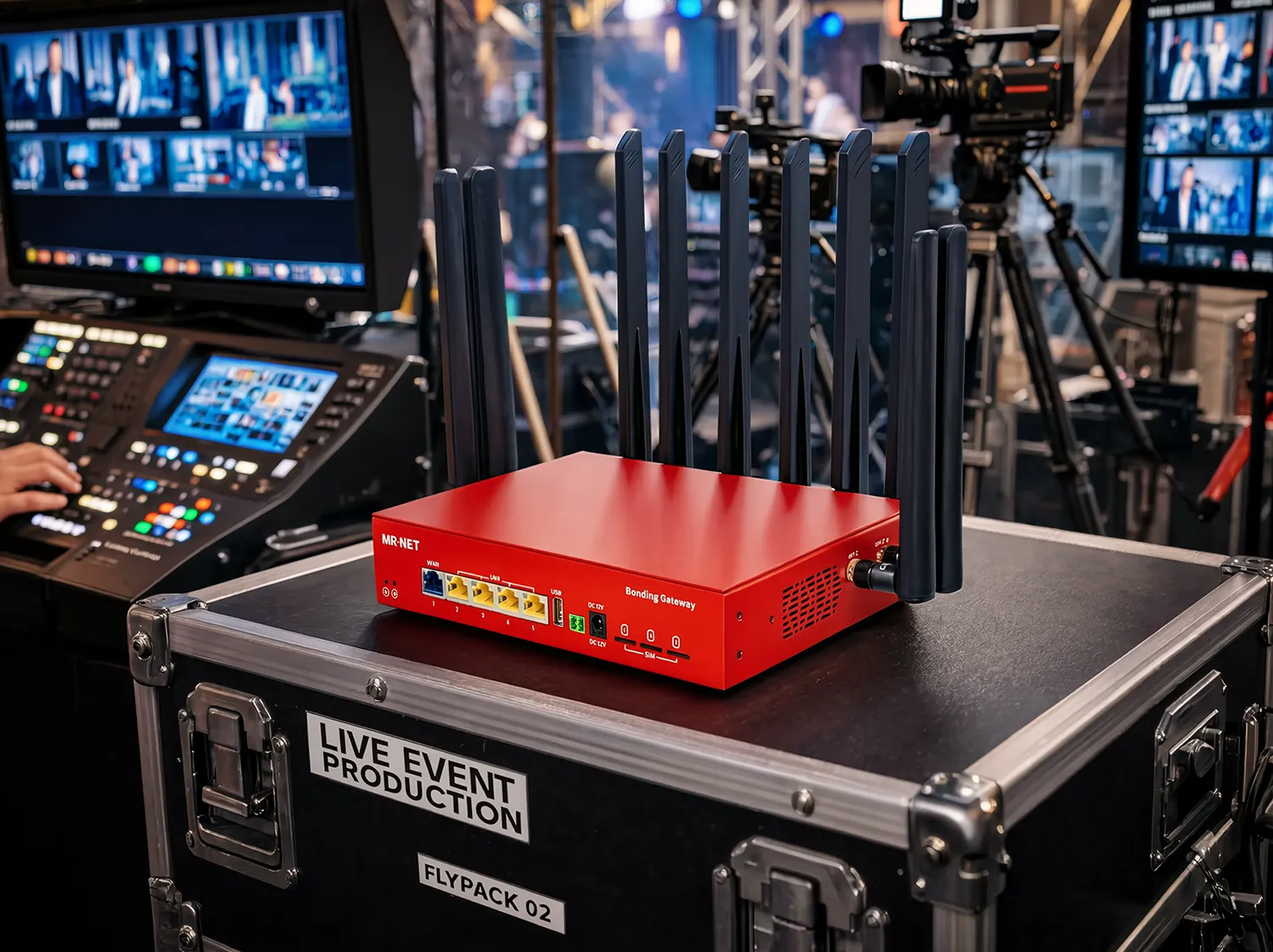
The MR·NET live events page covers what a managed, pre-configured cellular bonding setup looks like in a REMI production workflow.
Frequently Asked Questions
What are REMI production’s internet requirements?
It depends on stream count and codec. A single HD stream over SRT needs 2 to 8 Mbps upstream, a single 4K HEVC stream needs 20 to 80 Mbps, and a 6-camera REMI setup using HEVC needs 60 to 200-plus Mbps aggregate upstream. Those are real-world minimums, not headline numbers off a spec sheet.
How do you build reliable connectivity for remote production?
Use managed bonded cellular with active, real-time link health monitoring across carriers, not just a device holding multiple SIMs. That means dynamic packet distribution based on live latency and loss, session persistence across failures, and pre-negotiated enterprise-grade SIMs, backed by proactive NOC monitoring. Just as important: engineer your intercom, tally, and camera control signal paths with the same rigor as video, since those are the paths that usually get treated as an afterthought.
Is cellular bonding good enough for REMI broadcast?
Yes, if it’s managed multi-carrier bonding rather than a basic SIM bank. Drawing from three independent tower relationships (Verizon, AT&T, T-Mobile) means that if one is saturated, the other two keep contributing bandwidth, and session persistence keeps streams live through carrier transitions. A single congested carrier alone delivers roughly 1 Mbps usable upload under real event conditions, which is why the multi-carrier piece is what makes it viable.
Is 5G better than 4G for live production contribution?
Not necessarily. Most live “5G” deployments are 5G NSA, meaning the radio is 5G but the core network still runs on 4G LTE, so there’s no network slicing or QoS priority for broadcast traffic, and the theoretical speed advantage rarely shows up on upload in a congested venue. Across MR·NET’s own deployments, 4G LTE has consistently produced more stable upstream performance in crowded indoor venues, thanks to a denser, more mature tower footprint and upload allocation tuned for sustained throughput.
What’s the difference between a SIM bank and managed bonded cellular?
A SIM bank just holds multiple SIM cards with basic traffic distribution: no real-time link health monitoring, no enterprise SIM priority, no NOC support. Managed bonded cellular actively monitors link health across carriers, dynamically distributes packets based on live latency and loss, keeps sessions alive through carrier failures, and runs on pre-negotiated enterprise SIMs with proactive NOC monitoring behind it.
Why do REMI productions fail even with good equipment?
Most REMI failures are systems integration failures, not equipment failures. Teams carefully engineer video contribution but treat intercom, tally, and camera control signals as an afterthought running on an untested path, and director-to-camera IFB latency above 200ms visibly disrupts live performance. Many productions also run single-path contribution with no tested failover, instead of following the SMPTE ST 2022-7 standard for hitless failover between redundant IP paths.
___
Sources: Haivision 2026 Broadcast Transformation Report (March 2026); Broadcast Management Group / Andrew Ryback (May 2026); Open Broadcast Systems - PSA German Open case study (November 2024); EAR Professional Audio Video; Streaming Media / Carlos Jose Gonzalez Pinzon, Univision (September 2025); LTN Global; TVU Networks; Dejero Bonded Cellular White Paper (2025); SMPTE ST 2022-7; LiveU press release (November 2024); Epiphan / SRT Alliance bandwidth specifications.